Note 1 for Digital Circuit Project
Binary Numbers
Different from analog signals or circuits, digital circuits have only two types of signals: HIGH and LOW, which are usually represented in the circuits by low (e.g. 0v) and high voltages (e.g. 5v). These two types of signals could be well represented by binary number system.
Binary Number Introduction
We can understand the meaning of binary numbers using the name way we understand usual decimal numbers. Each digits of decimal numbers have different significance, for example:
Note that the base of these exponents are all 10, like . In decimal numbers, we change it to 2, and we get binary numbers. For example:
Converting Decimal Numbers to Binary Numbers
In the previous number, by the addition of different digits, we converted binary numbers to decimal numbers. Now we want to do the opposite thing, which is converting decimal numbers to binary numbers.
The steps are listed here:
- Find the largest power of 2 that is smaller than the decimal number
- Subtract the power of 2 from the decimal number
- Record the power of 2 as 1, and record 0 for all other powers of 2
- Repeat the first two steps until the decimal number is 0
For example, we want to convert 12 to binary numbers:
- The largest power of 2 that is smaller than 12 is
- , so we record 1 for and 0 for all other powers of 2, now we have
- The largest power of 2 that is smaller than 4 is
- , so we record 1 for and 0 for all other powers of 2, now we have
- Since the decimal number is 0, we stop here, and the binary number is
Here are some other examples:
Binary Arithmetics
Addition
For binary addtions, the rules are listed:
- 0 + 0 = 0
- 0 + 1 = 1
- 1 + 0 = 1
- 1 + 1 = 0, and carry 1 (sum of 0 with a carry of 1)
For exmaple, we can write the vertical addition of biiary 11 and binary 11 as follows:
Here the addition of least significant digit of 1 is 1 + 1 = 0 according to the rule, and it also produced a carry to the next digit.
On the next digit, we originally have 1 + 1 = 0, but we also have a carry of 1, so the addition is 1 + 1 + 1 = 1, and it also produced a carry to the next digit.
So the final result is 110, which is 6 in decimal numbers.
Subtraction
Since the ultimate goal for this project is to build some digital circuits, compare to addition, subtractions described in this part is not as important. This is because in real circuits, addtions and subtrations are implemented in the same way.
For binary subtractions, the rules are listed:
- 0 - 0 = 0
- 1 - 0 = 1
- 1 - 1 = 0
- 10 - 1 = 1, and borrow 1 (difference of 0 with a borrow of 1)
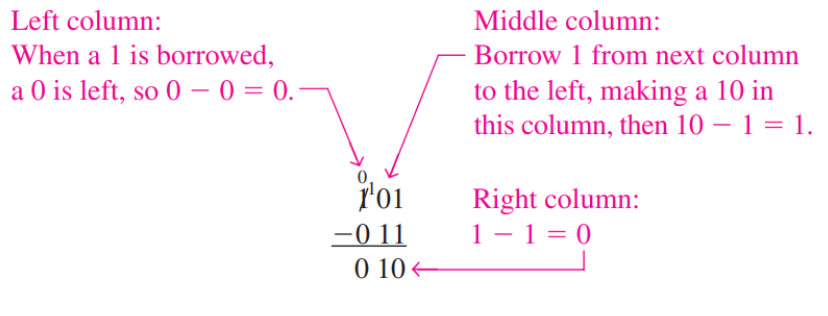
The following is an illustraion about the subtraction process.
Multiplication and Division
For multiplications, the ruls are:
- 0 x 0 = 0
- 0 x 1 = 0
- 1 x 0 = 0
- 1 x 1 = 1
If we write multiplications in verticle form, it is essentially adding up the result of previous rules with some shifts to the left.
For example, is:
Here, we write the second 11 with a shift to the left because we’re muliplying 11 and 10.
For multiplication of 10, it could be expressed as a shift to the left, which is essentially adding a 0 to the end of the number.
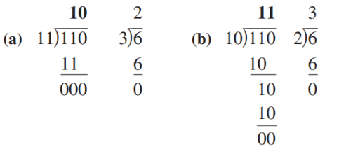
For divisions, the following illustration explained the process:
Signed Binay Numbers Representation and Arithmetics
The most widely used signed binary number representation is called two’s complement. In this representation, the most significant bit (MSB) is used to represent the sign of the number, and the rest of the bits are used to represent the magnitude of the number (but it is not the same way we used to represent magnitudes in unsigned numbers).
This representation allowed us to do subtraction and multiplication using the same set of hardware.
If we represent a binary number as , and its two’s complement as , then we have , essentially making two’s complement as the negative of the original number.
If we want to represent the negative of a binary number in two’s complement, we can do the following steps:
- Invert all the bits of the original number
- Add 1 to the result
Now we denote the bitwise inversion of a binary number as , then if we add and , we will have all the bits as 1. For example, if we have , then , and .
Adding another 1 to the result, we will have . Although we the most signficant bit setted to be 1, it exceeded the number of bits we used to represent the number, so we just ignore it, and we have , which is 0 in decimal numbers. This proofs the statement that the two’s complement of a number is the negative of the number.
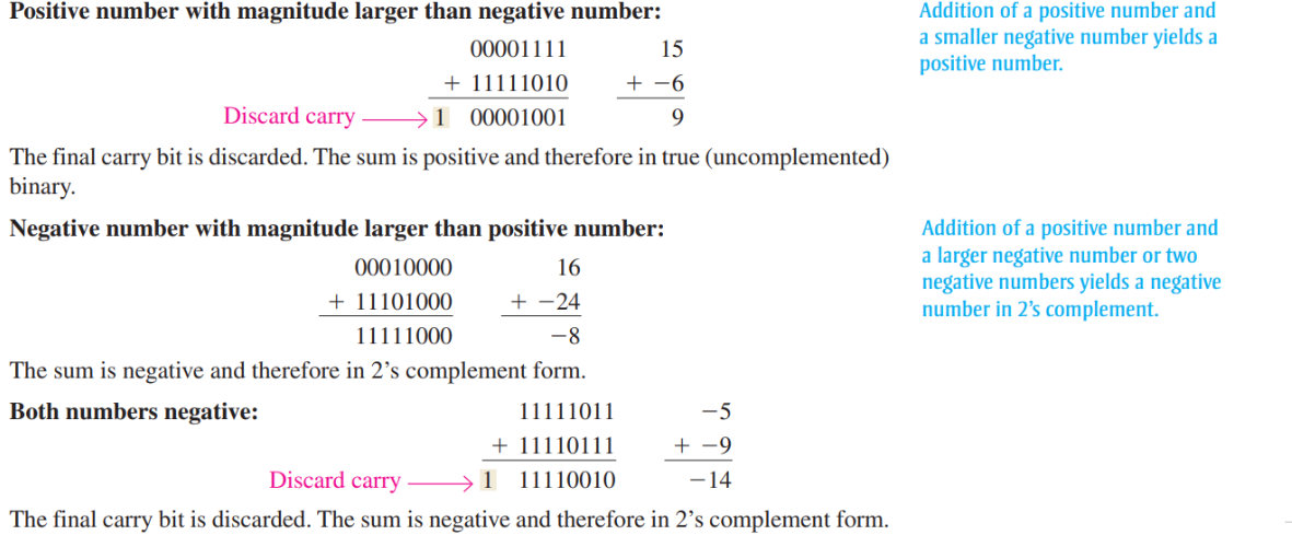
The following figure illustrated the most important idea behind two’s complement representation: modular arithmetic.
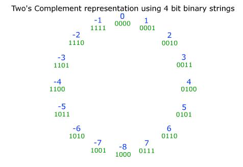
Consider 3 and -2 in the cricle and their binary representation 0111 and 1110. If we interprete these binary representations in the unsigned way, then we will get 3 and 14. Add them under modular operations like :
Here 16 indicate how many numbers are on the circle, and as expected, we get 1 as the result. The following is a more complete illustration of signed binary number addtions.
For multiplications, you can checkout this website:
https://pages.cs.wisc.edu/~markhill/cs354/Fall2008/beyond354/int.mult.html
Logic Gates
Logic gates are the building blocks of any digital circuit. They are essentially build up by transistors. But we won’t discuss how to build logic gates using transistors. If you are interested in, check: https://www.101computing.net/creating-logic-gates-using-transistors/
Logic’s input and outputs are HIGH or LOW voltage signals, which are represented by 1 and 0 respectively. If we enumerate the possible inputs and outputs, we will have a table called truth table, which defines the logic of the gate.
Inverter / NOT Gate
Inverters have one input and one output. The output is the inverse of the input. The truth table of inverter is:
| Input | Output |
|---|---|
| 0 | 1 |
| 1 | 0 |
And the graphical symbol of it is:
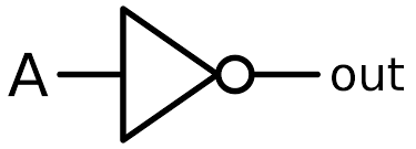
We represent this inversion operation as
Where X is the output, and A is the input.
AND Gate
AND gates have two inputs and one output. The output is 1 only when both inputs are 1. The truth table of AND gate is:
| Input A | Input B | Output |
|---|---|---|
| 0 | 0 | 0 |
| 0 | 1 | 0 |
| 1 | 0 | 0 |
| 1 | 1 | 1 |
And the graphical symbol of it is:
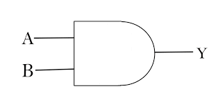
We represent this AND operation as
Where X is the output, and A and B are the inputs. This make sense becaue in multiplications, the output is 1 only when the two inputs are 1.
OR Gate
OR gates have two inputs and one output. The output is 1 when either of the inputs is 1. The truth table of OR gate is:
| Input A | Input B | Output |
|---|---|---|
| 0 | 0 | 0 |
| 0 | 1 | 1 |
| 1 | 0 | 1 |
| 1 | 1 | 1 |
And the graphical symbol of it is:
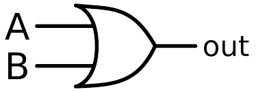
We represent this OR operation as:
Where X is the output, and A and B are the inputs. This make sense becaue in additions, the output is 1 when either of the inputs is 1.
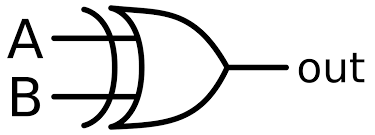
XOR gate
The full name of XOR is exclusive OR. It has two inputs and one output. The output is 1 when the two inputs are different. The truth table of XOR gate is:
| Input A | Input B | Output |
|---|---|---|
| 0 | 0 | 0 |
| 0 | 1 | 1 |
| 1 | 0 | 1 |
| 1 | 1 | 0 |
And the graphical symbol of it is:
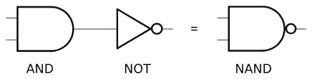
NAND and NOR
NAND and NOR are the negations of AND and OR respectively. They are also called universal gates because any logic can be implemented using them. The truth tables of NAND is:
| Input A | Input B | Output |
|---|---|---|
| 0 | 0 | 1 |
| 0 | 1 | 1 |
| 1 | 0 | 1 |
| 1 | 1 | 0 |
And the truth table of NOR is:
| Input A | Input B | Output |
|---|---|---|
| 0 | 0 | 1 |
| 0 | 1 | 0 |
| 1 | 0 | 0 |
| 1 | 1 | 0 |
The graphical symbols of NAND is:
And the graphical symbol of NOR is:
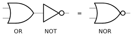
Notice the dot in the output side of the NAND and NOR symbols. It means that the output of the gate is inverted.
Implementation of Adders
It will be hard for us to think of addition using pure logic gates, but it will be easier if we start by considering one bit addition.
Half Adder
Recall the addition rules of binary numbers:
- 0 + 0 = 00
- 0 + 1 = 01
- 1 + 0 = 01
- 1 + 1 = 10
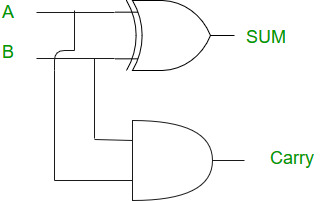
Now the addition of two bits can output a two-bit number. For the sum bit, the output will be 1 only when the two inputs are different. For the carry bit, the output will be 1 only when both inputs are 1.
We can see that the pattern for the sum bit is the same as the XOR gate, and the pattern for the carry bit is the same as the AND gate. So we can implement the half adder using XOR and AND gates:
Full Adder
In reality, we don’t add two bits at a time, we add multiple bits at a time. So we need to consider the carry bit from the previous addition. If carry in, input A and B are all 1, then the output should be 11. And now we can try to construct the circuit from the truth table:
| Input A | Input B | Carry In | Sum | Carry Out |
|---|---|---|---|---|
| 0 | 0 | 0 | 0 | 0 |
| 0 | 0 | 1 | 1 | 0 |
| 0 | 1 | 0 | 1 | 0 |
| 0 | 1 | 1 | 0 | 1 |
| 1 | 0 | 0 | 1 | 0 |
| 1 | 0 | 1 | 0 | 1 |
| 1 | 1 | 0 | 0 | 1 |
| 1 | 1 | 1 | 1 | 1 |
The circuit can be illustrated as:
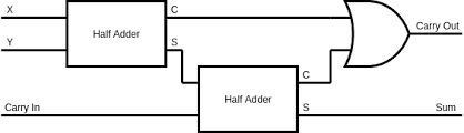
Notice the OR gate in the circuit. It is used to combine the two carry outs from the half adders. If either of the half adders has a carry out, then the output of the OR gate will be 1.
For example, 1(carry)0(sum) + 0(carry)1(sum) = 11, so the carry out of the first half adder is 1, and the carry out of the second half adder is 0. So the output of the OR gate is 1, and the final carry out is 1. Notice that it is impossible to have two carry outs set to be 1 at the same time, this can be observed through the chained structure of the two half adders.
With the full adder implemented, we can now add as many bits as we want. The following is an example of 3-bit adder: