Note 2 for Digital Circuit Project
Introduction to Logisim
Because of the inconvenience in porting large tangible circuit, to get access to circuits everywhere and avoid accidents, we introduce the application logisim as a powerful tool for circuit design. It can simulate the circuits on computer with easy moves.
Logisim Download
To get access to the circuits simulator, we need to download the software first. Here is the link to the website:
https://snapcraft.io/logisim-evolution
All you need to do is to choose the correct package and click download to get the file. Then install the file to your computer, and open it.
Test Gates in logisim
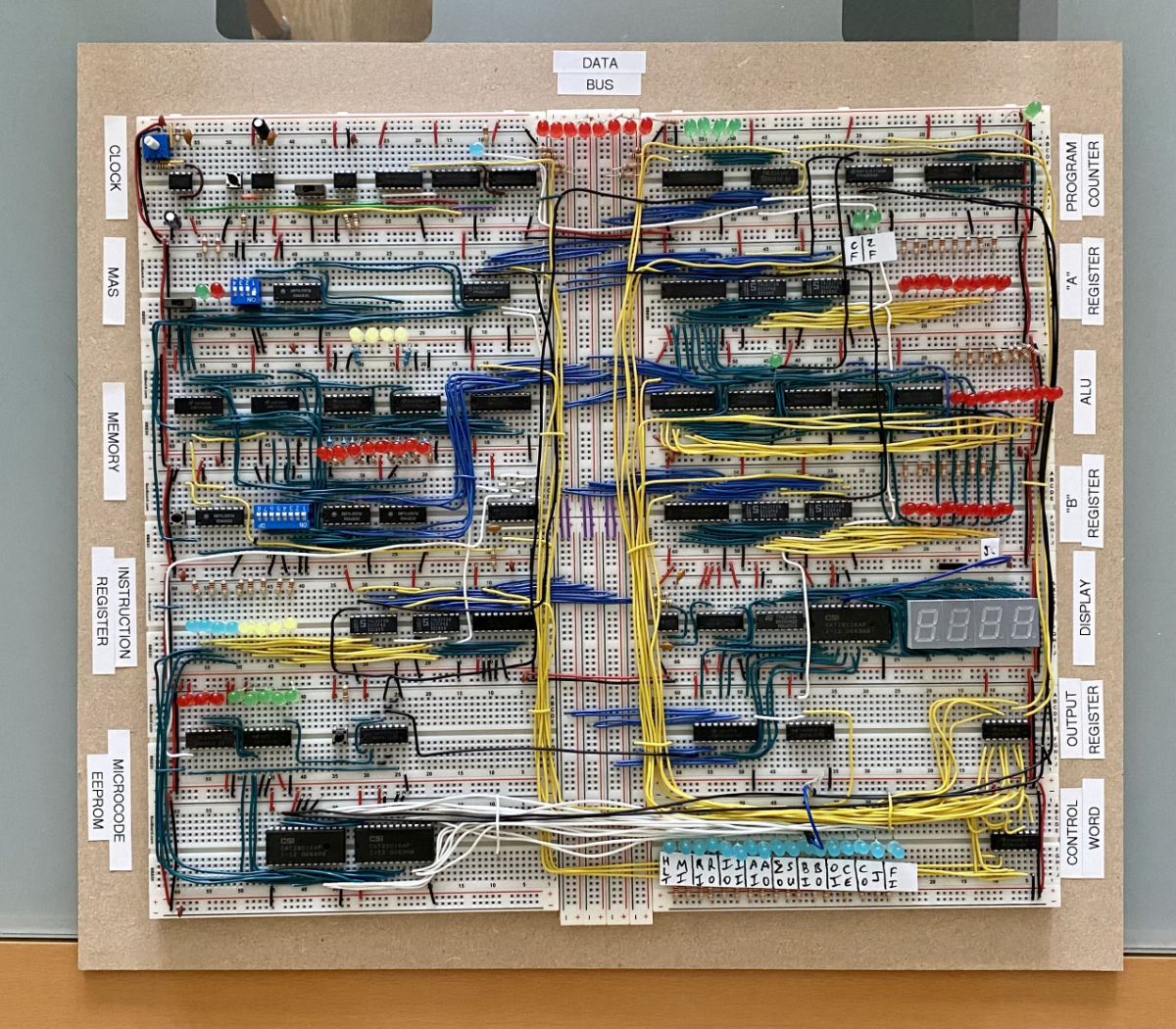
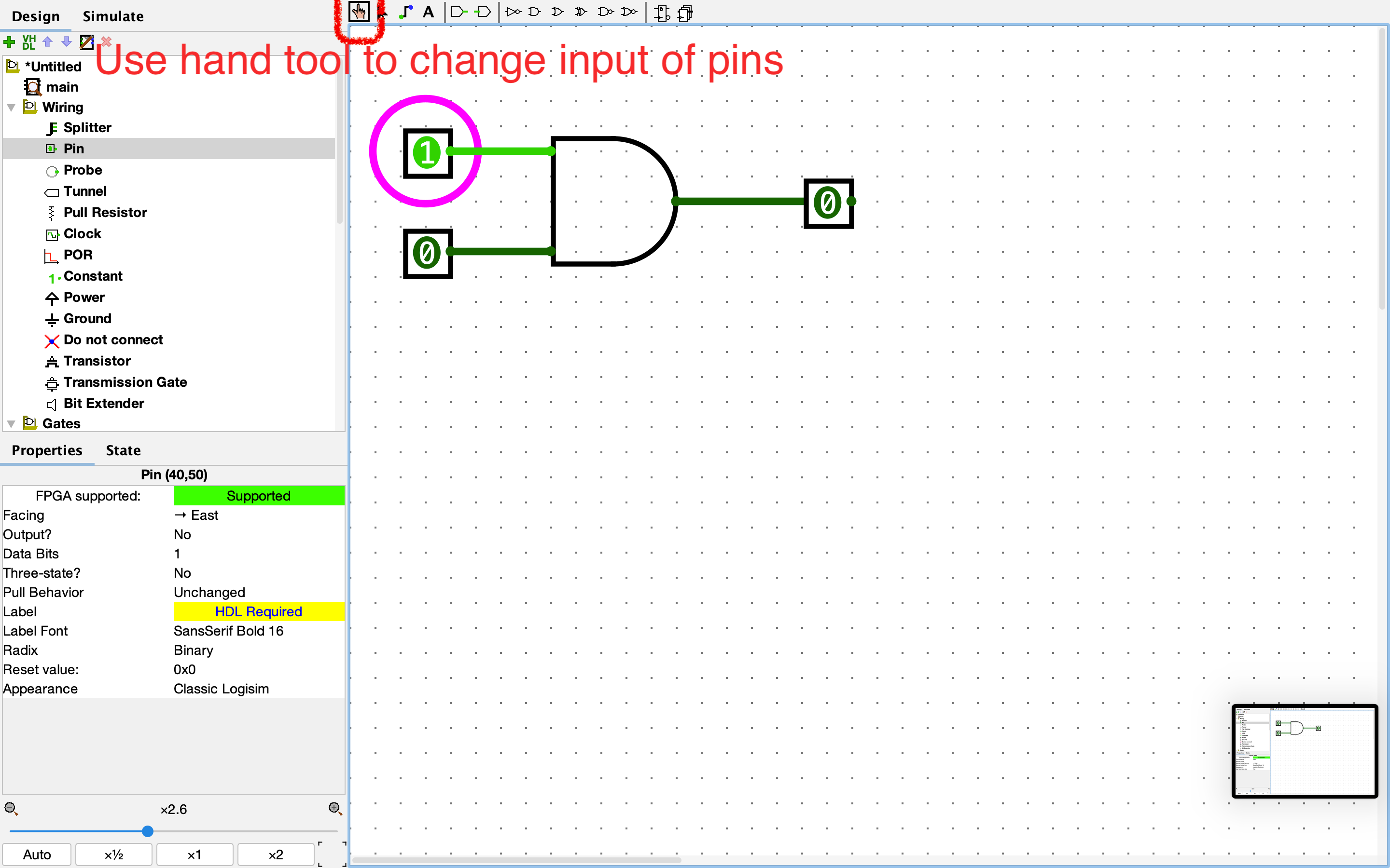
Find logic gates in “gates” section
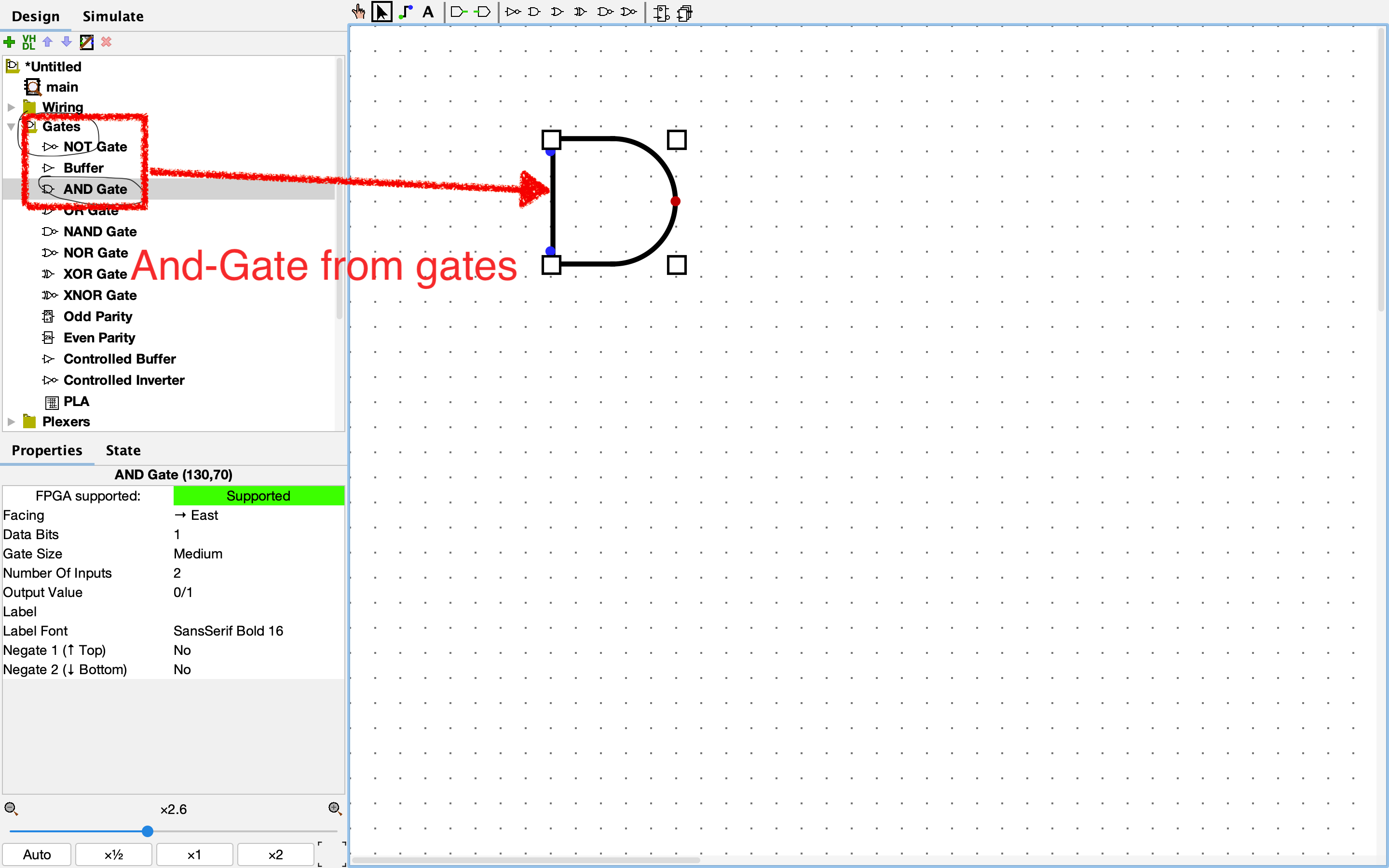
Find pin in “Wiring section
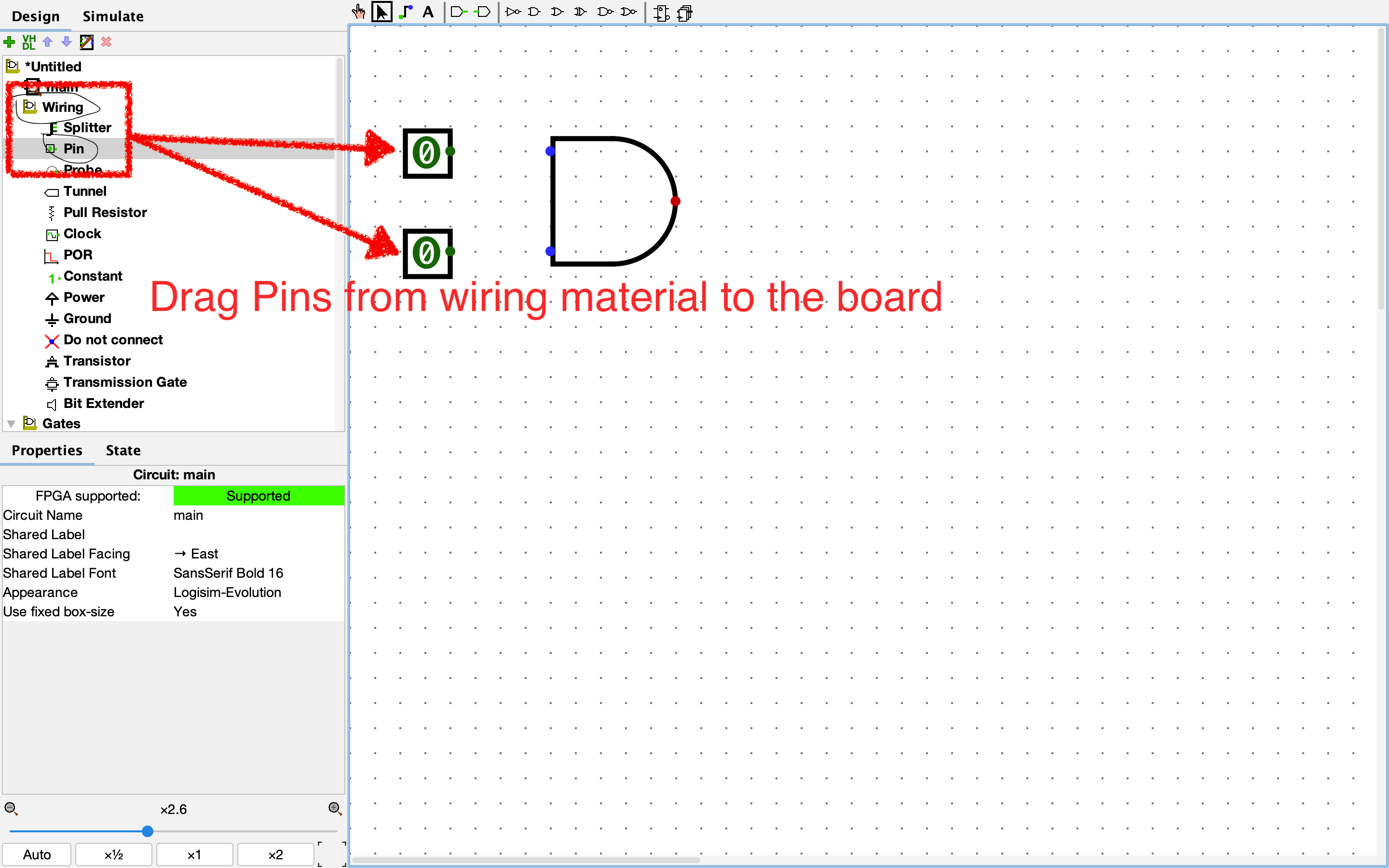
Connect wires use the “cursor” tool
Change inputs of pins using the “hand” tool
Light green indicates high signals
Little Exercise: Make a Half Adder
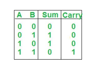
Half adder is a combination of two inputs and create a sum bit and a carry bit both as output. The sum output represents the least significant bits while the carry output represents the most significant bit, which means sum output is 1 as long as one of the input is 1, and the carry output is 1 if and only if both of them are 1.
Here is the truth table for you to check:
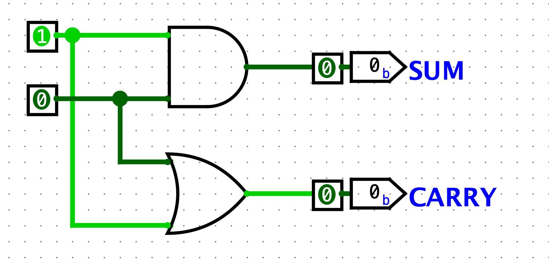
Here is the circuit that can perform such a function:
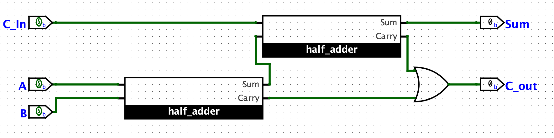
Implement the full adder
Using the half adder cicruit, we can easily make a full adder which gives C_out and sum that only become true when more than two true input or become true while one of the inputs are true respectively. Here is the circuit to make such a logic gate.
Make Hex number Display
Hex number as you might know is a kind of number that goes to the next digit after added up to 16, and it uses “A, B, C, D, E, F” to represent the numbers that bigger than 9 to make it’s rigid “one digit”. Here, we use the logism ciruit to make one hex number one digit displayer.
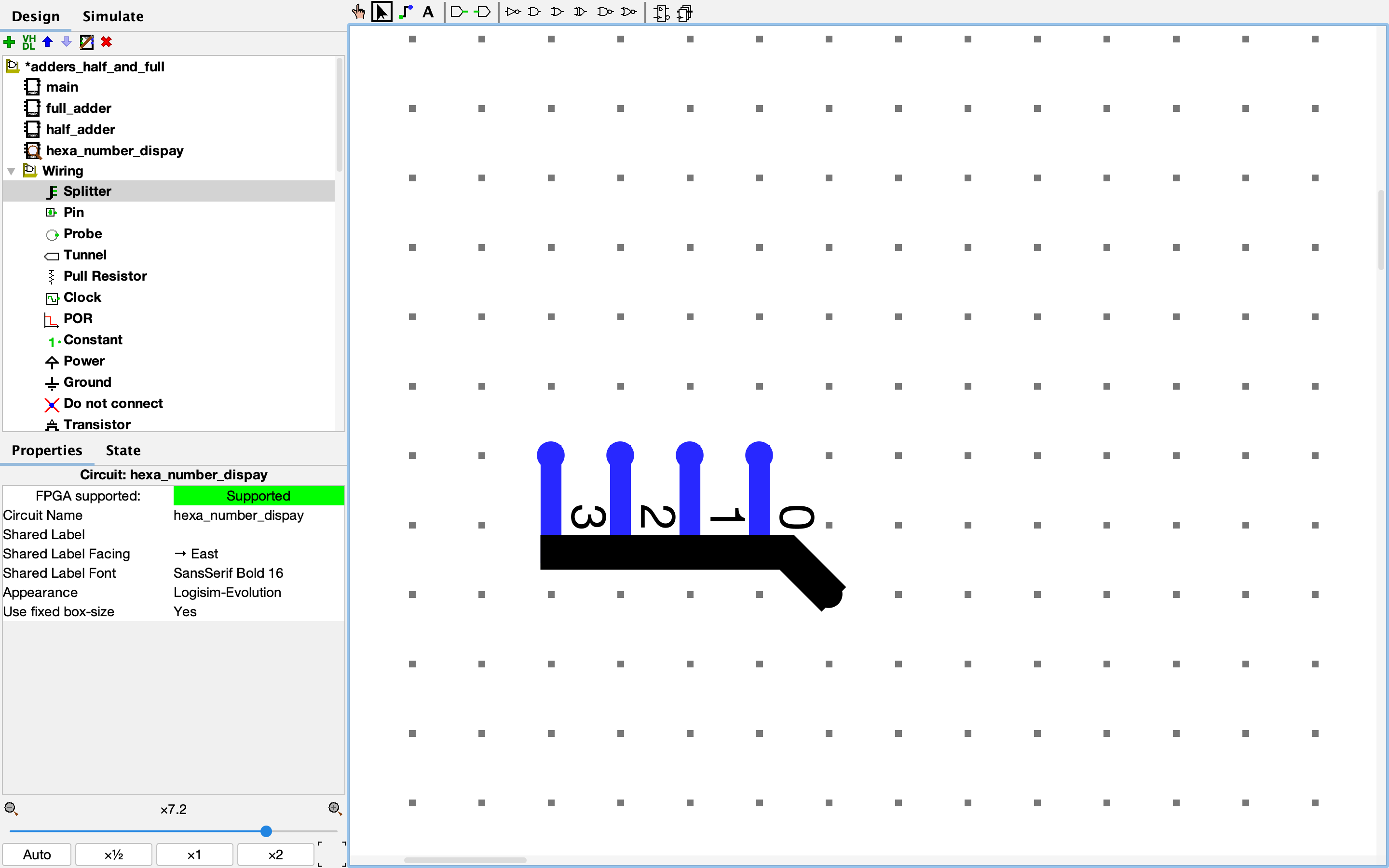
Learn to use Splitter
Use splitters (in wiring) to convert between multi-bit and single-bit wires. Darg the splitter out from wiring category, then adjust the facing to North, and bit number to 0 to 3 from left to right in the left bottom bar. Here is what is should look like after adjustment.
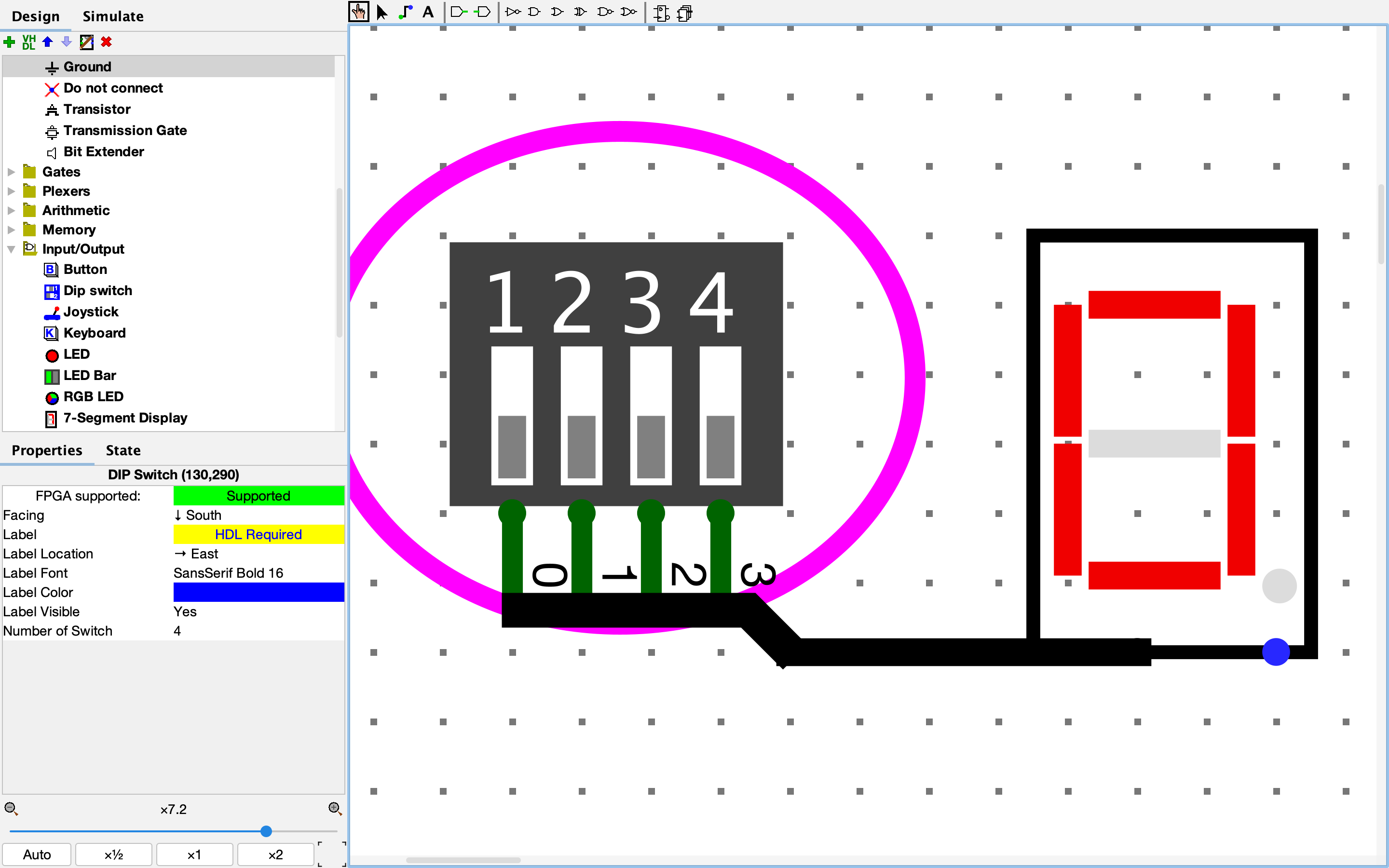
Make the Display
Based on the splitter file, pull out Dip Switch from I/O category and adjust its number of switch to 4. Then connect the dip switch to the splitter. Drug the hex digit displayer from I/O category and place it aside. Then switch the switches to see the changes of the hex number, and try to display from 0 all the way to F.
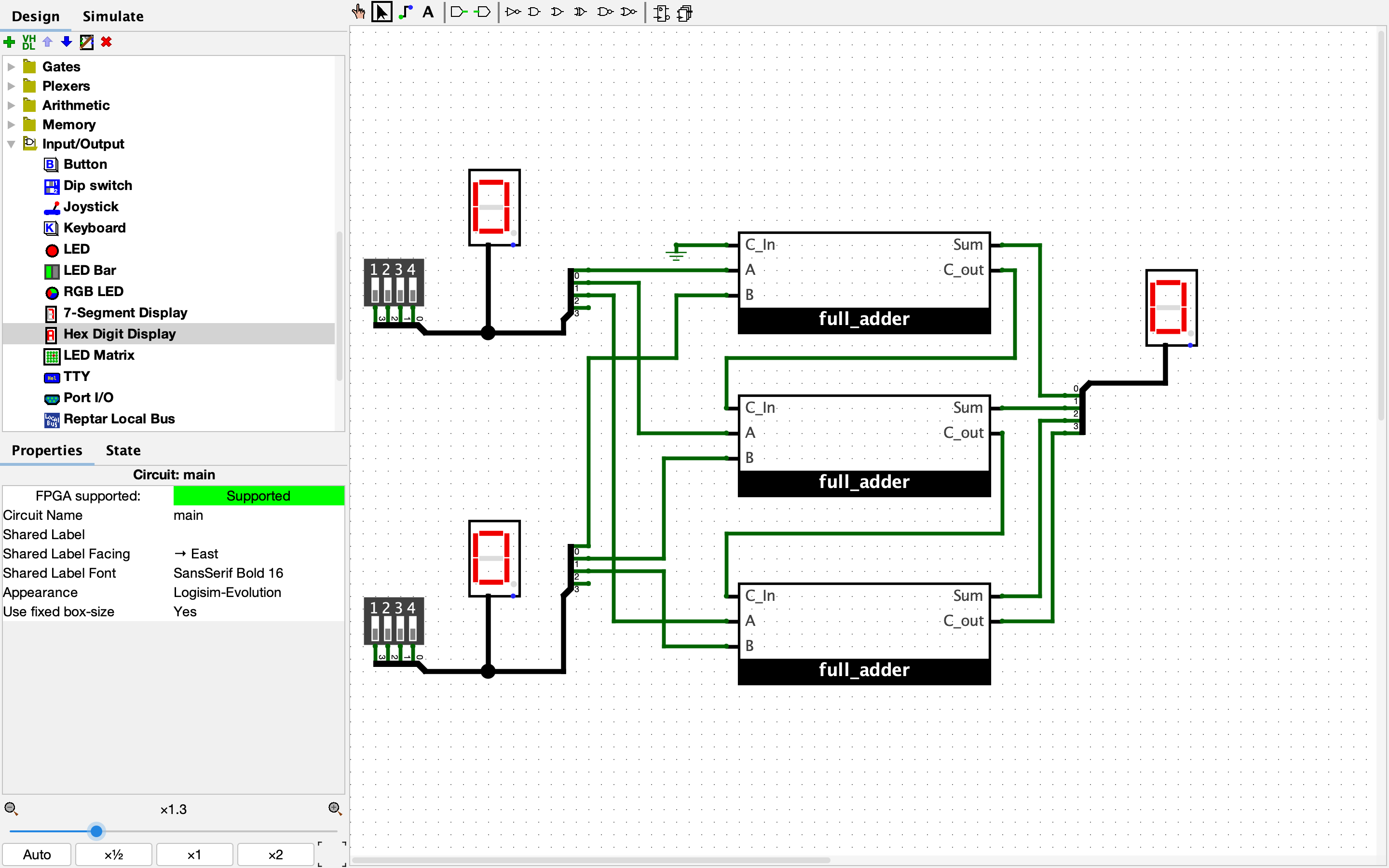
Challenge, Implement 3 bit adder
Try your best to make the circuit in the following graph, and test the truth table of it.
For more information, you can check out the digital circuit reference.